Teensy++ (AVR) PLC controller – version 1
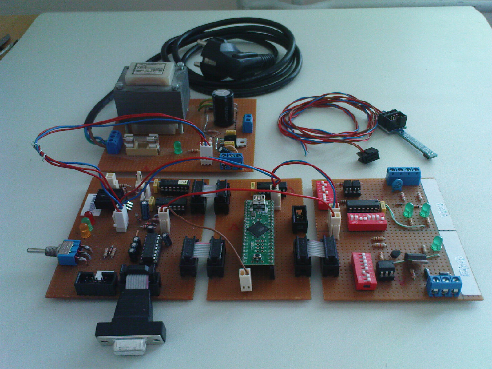
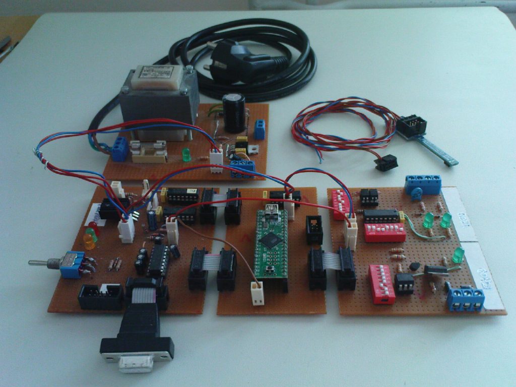
Here it is! The AT90USB646-based homebrew programmable logic controller. It’s not quite a Simatic S7 (and it’s not even completed in most parts), but it’s a nice start. A more complete and IEC-ish environment on the development software part (among many other things) would be nicer, but… the code is (will be) here, so extend it to whatever you want. But, whatever you may want to do with it, keep in mind it’s more of a “proof-of-concept” thing than a production-ready device.
Programming environment
Programming, compiling and flashing the controller is done in a graphical point-and-click environment. Anyone ever using any popular programming environment should feel comfortable from the start.
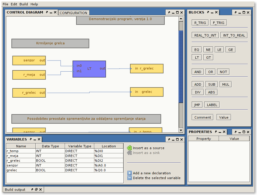
The programming environment
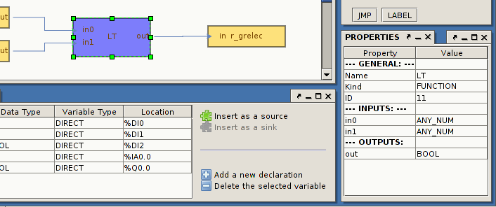
Properties tab
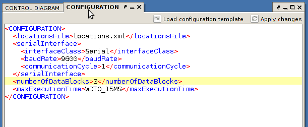
The PLC configuration panel
Sample program
Programming is done in an IEC FBD-like fashion. However, there is only one single program (cyclically executed) and available functions and function blocks are hard-coded into the environment. Variables are either local, global or direct. And each direct variable has some location assigned to it. Supported data types are BOOL, REAL and INT. Special internal locations are data blocks. Data blocks are integer variables that can be accessed and/or modified from outside through a serial connection.
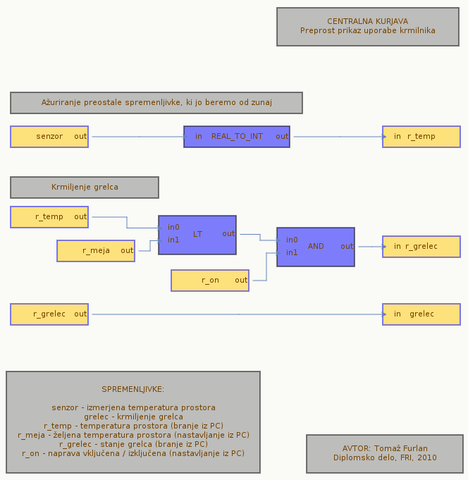
Sample control program – control diagram
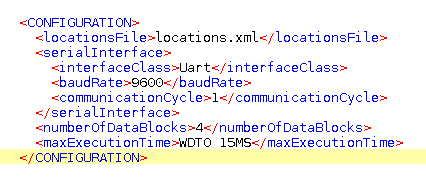
Sample control program – configuration

Sample control program – variable declarations
Locations
PLC modules are accessed through locations. In order to use external I/O modules, the user doesn’t have to know the electronic components and internals of modules or utilize any low-level programming. All the user needs are predefined textual xml definitions of module locations. Based on these definitions, the development environment transparently generates and includes all the neccesary low-level code into the program at compile-time.
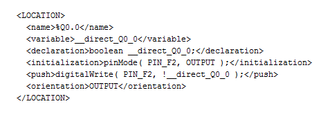
Digital output location sample definition
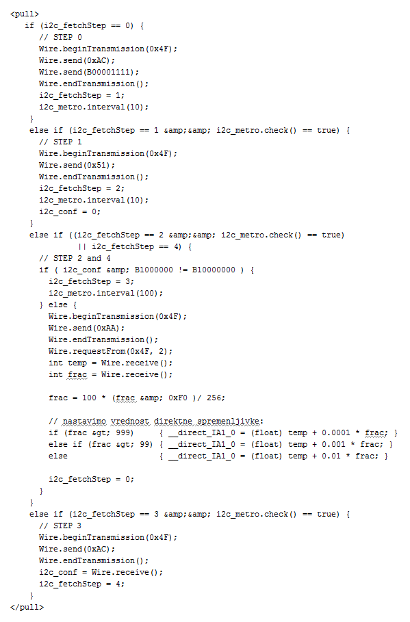
Part of location definition for Conrad C-Control I I2C thermometer module
Summary
- Programmable with a simple USB cable
- Serial communication to controller (accessing the controller data from outside) through USB or RS232
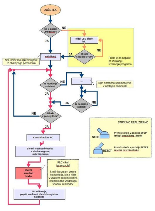
- Power failure handling (just in hardware/firmware, not yet supported by development environment)
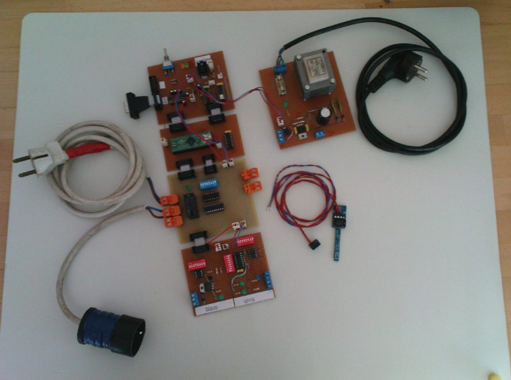
- Modular and extendable design – connecting to I/O modules through I2C, SPI or directly using the remaining MCU pins, support for extension I/O modules added to the IDE with textual XML definition files
- Integrated development environment on the PC
- Graphically programmable, configuration in XML
- Extension I/O modules accessed through locations (use of direct variables), no need to know the internals of connected modules
- Simple java library to access the controller
- Open source
- Firmware written in Arduino language (or C++ with Arduino libraries – as you may prefer to call it)
- Firmware compiles with avr-gcc and some scripts
- Realization as an Arduino shield should be easy, realization in a stand-alone PCB should be even easier
- Only some minor work should be necessary to adapt the firmware and IDE to ATMegas of Arduino
- Programabilni logični krmilnik (Programmable Logic Controller) – the original thesis text (in Slovenian)
Very nice work. I used to work with S7 PLC’s and even developed something similar for my undergraduate thesis (SFC language only). Looking forward to more details.
Would you go commercial with the project?
No such plans at the moment. Would you find such a simple controller commercially interesting?
To be honest, I think that it makes more sense developing a generic ladder logic software for the ARM processors (Cortex M0 and M3). They might focus now more on infotainemend but sensing and control capability will follow- for the M0 at low power. AVR and the Arduino might be something of the past.